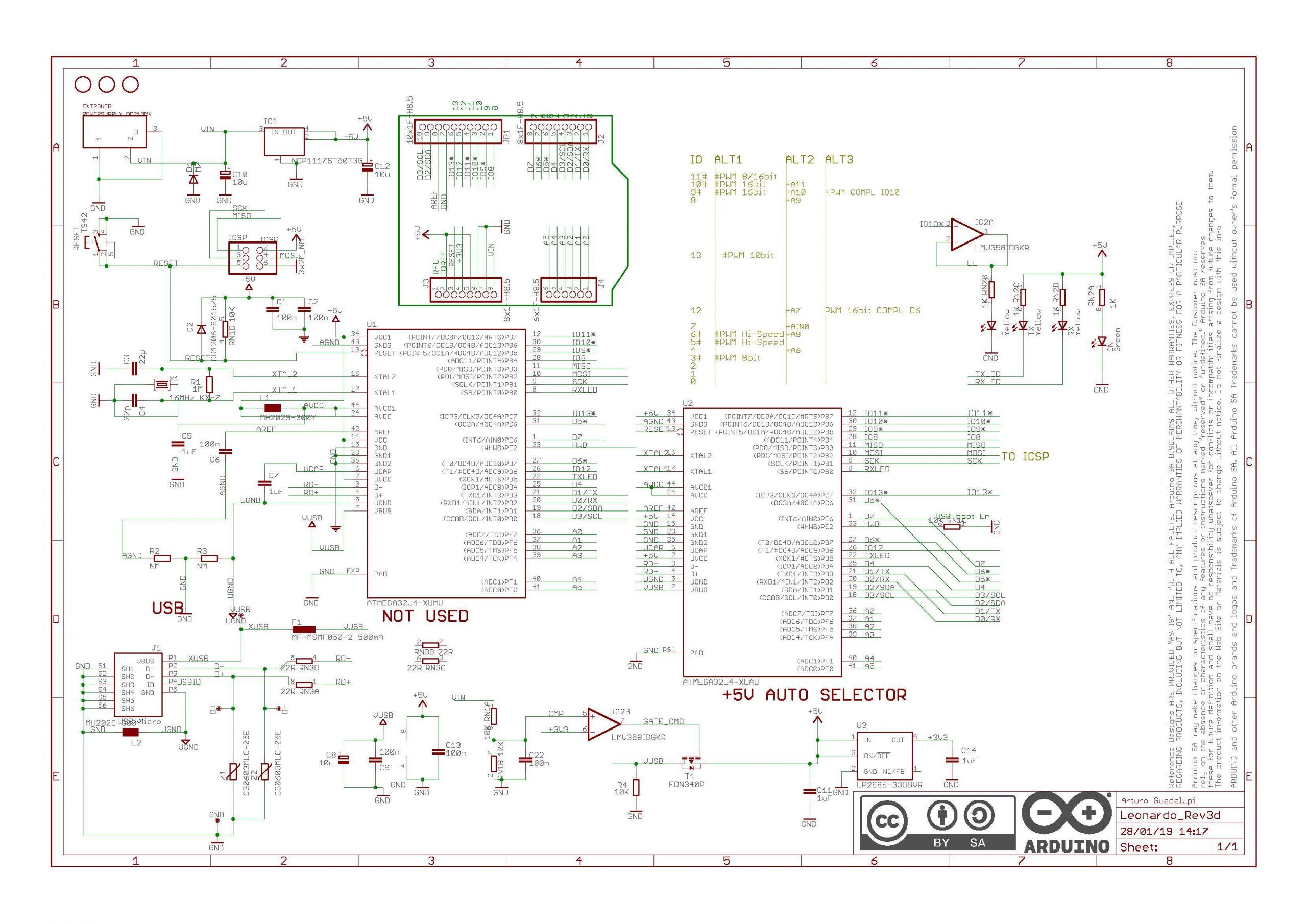

Table 4-5 lists the pin assignments for the Arduino Ethernet. Ethernet connectivity can be obtained by using anĮthernet shield (see Chapter 8 for more details on shields). This product has been retired by, but it is still available from Figure 4-18 shows the pinouts of the Ethernet board. On a right-angle six-pin header along one edge of the PCB next to the microSDĬarrier. The SparkFun or Adafruit FTDI-type devices. Arduino Ethernet block diagramĪn FTDI-type interface is used to program the Ethernet with an adapter, like

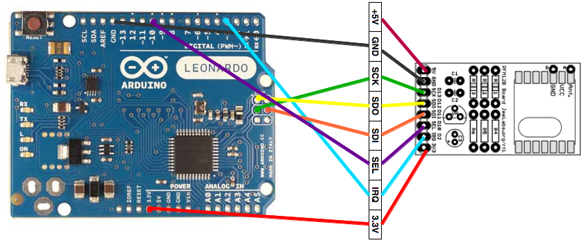
As shown in Figure 4-14, these pins are arranged as two eight-position connectors and two six-position connectorsįigure 4-17. Input pins, pins for 3.3V and 5V, and a reset line. The common baseline I/O and power pin layout for the Arduino consists of 14ĭiscrete digital I/O pins, an analog reference, 3 ground pins, 6 analog The grayīoxes in Figure 4-14 give the chip pin number and port designations This includes the Diecimila, Duemilanove, Uno R2, and Uno SMD models. Baseline layout Arduino boards Board nameįigure 4-14 shows the pinout of a full-size baseline Arduino board. The Arduino boards that utilize the baseline Over the years it has become a de facto standard upon which numerous The baseline Arduino pin layout as it exists today appeared with the Diecimila It has the same I/O pin layout as earlier boards,Īlthough the actual microcontroller ports used are different. The Leonardo PCB uses the ATmega32U4 processor, which hasīuilt-in USB support, so there is only one microcontroller IC on a Leonardo PCBĪnd only one ICSP port. The extension only adds new signal pin sockets,īut no new signals, and it doesn’t alter any of the pin functions found in theīaseline layout. Like a Duemilanove will still work with the newer boards. This is aīackward-compatible extension, meaning that a shield intended for an older model The Uno R3 introduced the new extended I/O pin configuration.

#Arduino leonardo vs mega serial#
This is the ICSP (In-Circuit Serial Programming) interface for theĪTmega16U2 processor that is used for the USB interface. The Uno R2 a new block of six pins appeared on the PCB, in addition to the block This book refers to this as the baseline Arduino form factor.

With the Diecimila, the Duemilanove, the Uno R2 (revision 2), and the Uno SMD theĪrrangement of the I/O socket headers along the edges of the PCBs is unchanged. The functions of the I/O and other pins on each PCB are described Layout that determines the physical design of most shields and other add-onĬomponents. Baseline, in this context, refers to the “classic” Arduino PCB In between there are the DuemilanoveĪnd Uno variants. Identical internally, and consist of a DC voltage regulation circuit and two ICs.įigure 4-1 shows a block diagram of the Diecimila and Duemilanove modelsįigure 4-4 shows the physical layouts for six different baseline Arduinoīoards, from the Diecimila to the Leonardo. Those boards that do not have a USB interface must be programmed using an externalĪrduino types that use the FTDI FT232RL serial-to-USB interface chip are essentially The operation of these parts is transparent when using the Arduino IDE to create In the Uno, Uno R3, and Mega2560 theĪdditional small ATmega processors are preprogrammed to serve as a USB interface. Standard serial (such as RS-232) and USB. The older Arduino models with USB used an FTDI interface chip (the FT232RL), anĪTmega8 (Uno), or an ATmega16U2 (Mega2560 and Uno R3). This part has a built-in USB interface, whichĮliminates the need for the additional chip seen on earlier Arduino models with a Starting with the Leonardo board (2012), the ATmega32U4 XMEGA microcontroller has been Arduino hardware features Board nameĬ Pulse-width modulation outputs (alternate DIO pin functions). Position on a 0.1 inch (2.54 mm) socket header, or the pins extending from theīottom of a shield PCB. “pin” as a connection point of some sort, be it a lead on an IC package, a Shields that plug into these sockets are the actual pins. The connection points on an Arduino board are sockets, and the jumpers and Terminology encountered elsewhere, but it’s not completely technically correct. This is mainly to maintain consistency with the The term “pin” is used in this and other sections when referring to the


 0 kommentar(er)
